User Tools
Sidebar
This is an old revision of the document!
Table of Contents
OpenWRT Simple VLAN Routing
Overview
This will configure an OpenWRT router from default configuration to enable two routed VLANs:
- VLAN ID 1 - 192.168.1.0/24 ↔ VLAN ID 101 - 192.168.101.0/24
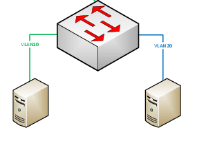
The final configuration will resemble this simple network diagram:
Configure VLAN tagging/untagging
Note: When configuring your OpenWRT router for VLAN support it is important to remember that once you configure a VLAN tag on a switch port you must use VLAN tags on all switch ports which will require you to reconfiguring the br-lan bridge to bridge directly to the primary VLAN rather than to the physical interface.
Login to the OpenWRT router:
- Set the root password
- Enable the wireless connection (recommended so that you don't get locked out of your router as the wireless LAN will continue to function even if you mess up your switch port configuration).
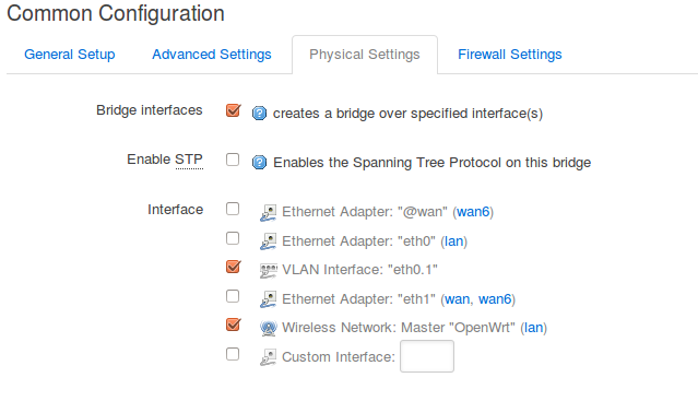
Change the primary interface for br-lan to bridge to VLAN 1
- Click 'Network' → 'Interfaces'
- Click 'Edit' on the LAN interface
- Click 'Physical Settings'
- Check the box next to 'VLAN Interface: “eth0.1”' (could also be eth1.1 depending on device)
- Uncheck the box next to 'Ethernet Adapter: “eth0”' (could also be eth1 depending on device)
- Click 'Save & Apply'
Configure VLAN tagging/untagging on all switch ports
Note: When routing between VLANs the CPU port must be set to tagged for all VLANs you intend to route between. Think of it like an internal trunk port.
- Click the 'Network' menu → Click 'Switch'
- Configure VLAN 1 (default VLAN for router switch ports)
- Change the drop down menu for the CPU port on VLAN ID 1 to 'tagged'
- For any switch port that you intend to designate to a specific VLAN change the drop down menu for that port to 'off'
- All remaining ports should be set to 'untagged' to allow those ports to communicate on VLAN 1
- Configure VLAN 101
- Click 'Add'
- Enter 101 in the 'VLAN ID' box
- Change the drop down menu for the CPU port on VLAN ID 101 to 'tagged'
- For any switch port that you intend to designate to this VLAN change the drop down menu for that port to 'untagged'
- All remaining ports should be set to 'off' to allow those ports to communicate on the default VLAN
- Click 'Save & Apply'
Create VLAN interface(s)
Now that you have configured VLAN tagging/untagging on your switch ports you must create a new interface for each new VLAN if you plan to route between them.
- Click the 'Network menu → Click 'Interfaces'
- Click 'Add new interface'
- Enter 'VLAN101' as the name of the interface
- Leave the protocol drop down box set to 'Static address'
- Click the radio button next to 'VLAN Interface: “eth0.101” (could also be eth1.101 depending on device)
- Click 'Submit'
- Enter an IPv4 address such as: 192.168.101.1
- Select an IPv4 netmask such as: 255.255.255.0
- If you want your router to handle DHCP leases for the new VLAN click the 'Setup DHCP server' button
- Click 'Save & Apply'
Configure Firewall
The final step to configuring your routed VLANs is to create firewall rules that will allow traffic to be forwarded between the virtual interfaces on the router
- Click the 'Network menu' → Click 'Firewall'
- Under 'Zones' click the 'Add' button
- Enter 'VLAN101' in the 'Name' box
- Set the 'Input', 'Output', and 'Forward' drop down menus to 'accept'
- In the 'Covered networks' section check the box next to 'VLAN101'
- Next to 'Allow forward to destination zones' check the 'lan' and 'wan' boxes
- Next to 'Allow forward from source zones' check the 'lan' box
- Click 'Save & Apply'
That's it, the router should now be configured to route between both VLANs!


